Fusion 360 post processor improvements for Wazer Desktop

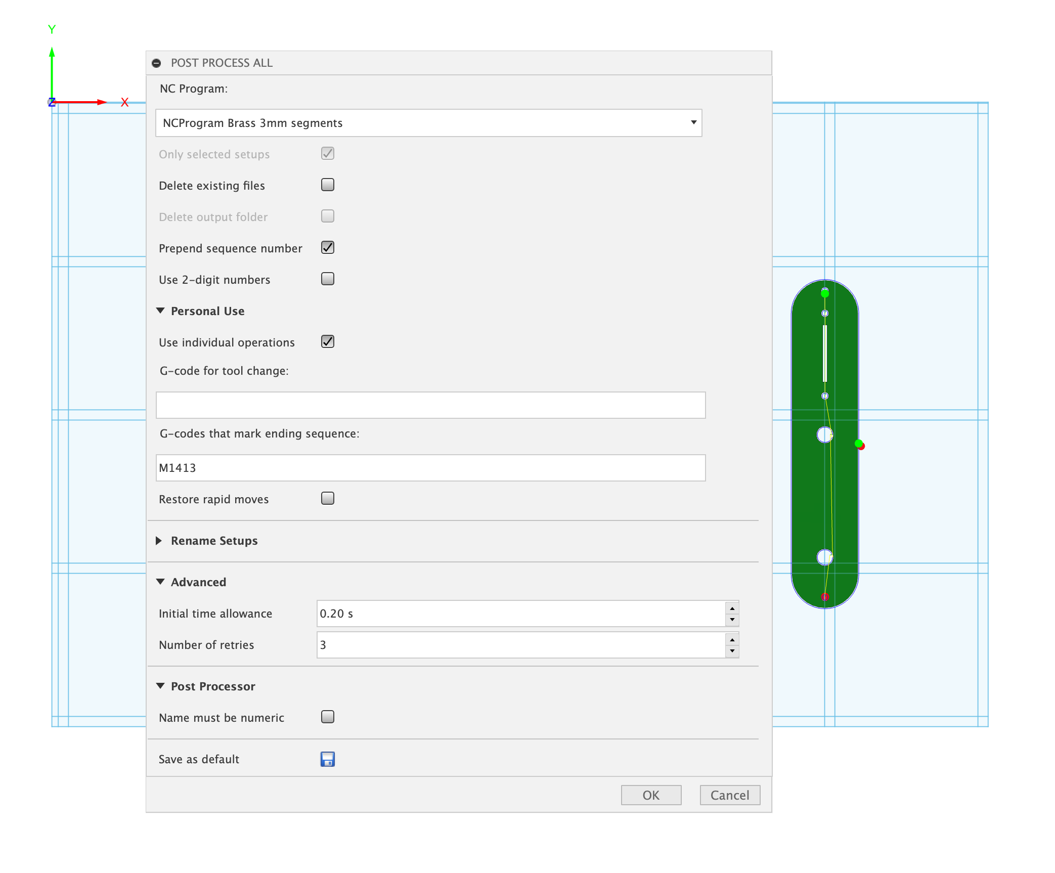
I recently picked up a Wazer Desktop second hand and wanted to generate gcode for it from Fusion 360. I noticed there is an existing post processor for it in Autodesk’s library. I was hoping to make some improvements to that code.

One improvement I’d like to see, and it’s one that is applicable to both Fusion 360’s post processor and the “WAM” web based app, is to get more granular feed recommendations.

Currently Wazer maintains a list of materials along with their recommended feeds & pierce times but these are only published for specific thickness. It’s my impression that these are based on formulas Wazer is not publishing directly but are fairly trivial to plot and fit functions to. I’ve gone ahead and mapped most of the materials to functions and updated the Fusion 360 post processor to look at the material thickness of the body used in the manufacturing setup and in turn apply these per-material functions so you don’t have to calculate feedrates by hand.

Here are “Fine” and “Rough” feedrate functions for 6061 Aluminum where the X-Axis is thickness in mm and the Y-Axis is feedrate in mm/m:

Here’s a pierce time function for 6061 Aluminum where the X-Axis is thickness in mm and the Y-Axis is time in seconds:

These functions appear to be close enough to match the thicknesses listed and allow one to select a material thickness not published by Wazer and get something that appears to be on the curve. For example, 11 gauge Aluminum being approx 0.09”/2.3mm seems to have fine-rough feedrate ranges in the ballpark of 43mm/m to 55mm/m.

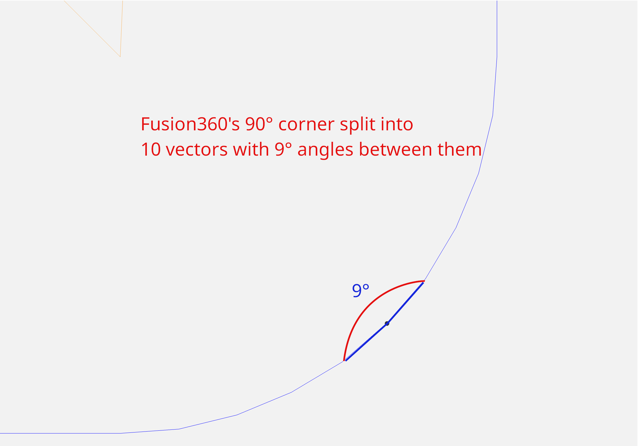
Another improvement I’d like to see is around the actual gcode being output by Fusion 360. I’ve read a few of the threads, including this recommendation from Wazer about “corner compensation”: Please fix wam! - #61 by Alex . And note that while Fusion 360’s 2D Profile does have some built in functionality for “Feed Optimization” which sort of speaks to this, it also appears to have some limitations:

  • One limitation is that it requires you have to specify the “Reduce Feedrate” in ipm or mmpm instead of something like a “Reduction Percentage” which at minimum means you have to specify feeds twice.
  • Another perceived limitation is that it does not progressively slow into the corners but rather goes from the normal cutting feedrate down to the reduced feedrate in one jump. I don’t know how critical this is in practice, but i noted that the gcode generated by WAM seems to do this progressive slow down into corners.
  • Yet another perceived limitation is that it does not progressively ramp back up to the feedrate when exiting a corner. Again, I don’t know how critical this is in practice, but I noted that the gcode generated by WAM seems to do this.

I’d like to improve feed optimization / corner compensation in Fusion 360. I’m curious if Wazer is interested in collaborating on this, and other such improvements in hopes of making Fusion 360 a more viable option for folks that have these machines. I suspect that the closed nature of the ecosystem is likely motivated by the desire to safely run these machines for the hobby crowd they appeared target towards, as well as to limit warranty concerns over software you don’t directly support. But it seems from this quote in the thread above there is in fact some openness to collaboration with third parties:

We would be happy to work with LightBurn on getting the concerns above mitigated

As my machine is second hand and presumably outside of warranty, I’ve already made and tested some modifications to the Fusion 360 post processor in hopes of getting closer to the “corner compensation” mentioned above. It’s WIP but I’m able to generate gcode that does take corners into consideration and progressively slows similar to what I’ve observed in the gcode generated by WAM.

I suspect this corner compensation functionality should be more or less attainable by modifying the Fusion 360 post processor alone, if we have a clearer understanding of the underlying algorithm. Or at least a clearer picture of the desired output and parameters to consider. I presume material, and thickness of material, as well as the inside angle of the corner are some of those parameters. Some of these considerations I’m sure can be deduced by reverse engineering the WAM generated gcode but if we could collaborate that may be a more fruitful, and less error prone path.

Here’s an example of a 1”x1” square cut from 2mm 6061 Aluminum generated by WAM:

;-------------------------------Cut file parameters------------------------
; Input file name : 25mm square ish.svg
; File rotation : 0 File scale : 3.8400000000000007
; Machine : Desktop
; Material name : Aluminum - 6061
; Material thickness : 2 mm
; Cut path : Outside
; Cut quality : mediumRate
; Raw Material width : 1.07in
; Raw Material height : 1.04in
;-------------------------------Do Not modify the Gcode file---------------
G90
G21
M1403
M1405 X215.31 Y-139.56
M1406 X242.48 Y-165.98
M1407 S9.72
M1410 2.1.0; Generated on Wam
M1411 Aluminum - 6061
M1412 2 mm
G0 X242.26 Y-141.25
M3
M8
G4 S9.72
G1 X242.17 Y-141.26 F56.02
G1 X242.08 Y-141.28 F39.21
G1 X241.99 Y-141.32 F47.62
G1 X241.92 Y-141.37 F39.21
G1 X241.85 Y-141.44
G1 X241.80 Y-141.51
G1 X241.76 Y-141.60
G1 X241.74 Y-141.69
G1 X241.73 Y-141.78
G1 X241.73 Y-146.04 F44.82
G1 X241.73 Y-150.29 F50.42
G1 X241.73 Y-152.77 F56.02
G1 X241.73 Y-157.77
G1 X241.73 Y-162.77 F47.62
G1 X241.73 Y-165.68 F39.21
G1 X241.58 Y-165.83
G1 X241.43 Y-165.98
G1 X236.43 Y-165.98 F47.62
G1 X231.43 Y-165.98 F56.02
G1 X228.52 Y-165.98
G1 X223.52 Y-165.98
G1 X218.52 Y-165.98 F47.62
G1 X215.61 Y-165.98 F39.21
G1 X215.46 Y-165.83
G1 X215.31 Y-165.68
G1 X215.31 Y-160.68 F47.62
G1 X215.31 Y-155.68 F56.02
G1 X215.31 Y-152.77
G1 X215.31 Y-147.77
G1 X215.31 Y-142.77 F47.62
G1 X215.31 Y-139.86 F39.21
G1 X215.46 Y-139.71
G1 X215.61 Y-139.56
G1 X220.61 Y-139.56 F47.62
G1 X225.61 Y-139.56 F56.02
G1 X228.52 Y-139.56
G1 X233.52 Y-139.56
G1 X238.52 Y-139.56 F47.62
G1 X241.43 Y-139.56 F39.21
G1 X241.58 Y-139.71 F42.02
G1 X241.73 Y-139.86 F28.01
G1 X241.73 Y-139.86
G1 X241.73 Y-139.86
G4 S1.
M9
G4 S1.
M5
G4 S1.
M1413 00:02:15
M1404

Here’s an example of a 1”x1” square cut from 2mm 6061 Aluminum generated by Fusion 360 with the WIP Wazer Desktop post processor described above:

;-------------------------------Cut file parameters------------------------
;Input file name : 1inch square v1
;Material name : Aluminum6061
;Material thickness : 2.000MM
;Cut Time: 1m:54s
;-------------------------------Do not modify the Gcode file---------------
;Machine
; vendor: Wazer
; model: Wazer Desktop
; description: Waterjet
G90
G21
M1403
M1405 X216.332 Y-140.734
M1406 X241.732 Y-166.134
M1407 S9.64
M1410 1.2

;2D Profile3 2
;Cut path : left
;Cut quality : Medium
G0 X243.599 Y-141.656
M3
M8
G4 S9.64
G1 X242.862 Y-141.656 F40.529
G1 X242.354 Y-141.656 F39.609
G1 X242.354 Y-156.134 F55.657
G1 X242.354 Y-166.134 F51.271
G1 X242.347 Y-166.231 F39.462
G1 X242.324 Y-166.326
G1 X242.286 Y-166.417
G1 X242.235 Y-166.500 F38.971
G1 X242.172 Y-166.574
G1 X242.098 Y-166.637
G1 X242.015 Y-166.688
G1 X241.924 Y-166.726 F39.515
G1 X241.829 Y-166.749
G1 X241.732 Y-166.756
G1 X226.332 Y-166.756 F55.673
G1 X216.332 Y-166.756 F51.271
G1 X216.235 Y-166.749 F39.462
G1 X216.140 Y-166.726
G1 X216.049 Y-166.688
G1 X215.966 Y-166.637 F38.971
G1 X215.892 Y-166.574
G1 X215.829 Y-166.500
G1 X215.778 Y-166.417
G1 X215.740 Y-166.326 F39.515
G1 X215.717 Y-166.231
G1 X215.710 Y-166.134
G1 X215.710 Y-150.734 F55.673
G1 X215.710 Y-140.734 F51.271
G1 X215.717 Y-140.637 F39.462
G1 X215.740 Y-140.542
G1 X215.778 Y-140.451
G1 X215.829 Y-140.368 F38.971
G1 X215.892 Y-140.294
G1 X215.966 Y-140.231
G1 X216.049 Y-140.180
G1 X216.140 Y-140.142 F39.515
G1 X216.235 Y-140.119
G1 X216.332 Y-140.112
G1 X231.732 Y-140.112 F55.673
G1 X241.732 Y-140.112 F51.108
G1 X241.812 Y-140.117 F39.273
G1 X241.890 Y-140.132 F39.172
G1 X241.966 Y-140.157 F39.072
G0 X241.966 Y-140.157
G4 S1.
M9
G4 S1.
M5
G4 S1.
M1413 00:01:54
M1404

I’ve simulated the Fusion 360 generated gcode in ncviewer and was confident enough to test it on my machine. To me the results seem comparable to the WAM generated gcode for this specific test case.

Thanks in Advance for your consideration.

1 Like

For curve compensation, if you open up WAM and inspect the page in your browser and open up the main.js file, you can actually see how they do it. It’s a little complex, and I’m not sure how easy it would be to implement into the Fusion 360 post-processor.

The super basics are:

// Angle calculation between path segments
yt = 180 * We.acos((Ut[0] * ci[0] + Ut[1] * ci[1]) / (tn * fo)) / i;

// Feed rate reduction based on angle
if (yt > 20 && yt < 60) {
    en[Tt - 1] && en[Tt - 1] > .85 && (en[Tt - 1] = .85),
    en[Tt] = .7,  // Reduce to 70% for 20-60 degree curves
    en[Tt + 1] = .85
} else if (yt >= 60) {
    en[Tt - 2] && en[Tt - 2] > .85 && (en[Tt - 2] = .85),
    en[Tt - 1] && en[Tt - 1] > .65 && (en[Tt - 1] = .65),
    pn < De && (en[Tt] = .45),  // Reduce to 45% for sharp curves (>60 degrees)
    en[Tt + 1] = .65,
    en[Tt + 2] = .85
}

So for a shallow curve (20-60 degrees), it goes from 100% feed to 85% before the curve, 70% during the curve, then up to 85% and then 100% after the curve.

For a sharper curve (60+ degrees), it goes from 100% to 85% to 65% to 45% before the curve, 45% during the curve, then up to 65% to 85% to 100% after the curve.

I think each change in feed rate is one segment in length. My understanding is that you take the previous two points, find their line, then compare that line to the line from the current point to the previous point, and use that angle.

It also pays attention to short segments, 0.05 in length. Less than 0.05, and it reduces the feed rate by 0.05 until it reaches 0.7, and then holds that feed rate.

And at the end of a cut path, I believe it reduces to 75% feed rate.

Ah, yes, of course. I should have thought of just gleaning that from their frontend code. Thanks for pointing that out!

In the post processor, I’m currently buffering the moves in onLinear and onRapid, then stepping through them in the onSectionEnd function. This allows the post processor code to look ahead / look behind to determine the current angle of the segment we’re either approaching, or leaving (θ being the acos of the dot product of the vectors). So it should be pretty straightforward to apply WAM’s angle thresholds and feed reduction factors. I initially set these as properties that the user could tune but they could just as easily be based on the values in the code snippet from main.js.

Thanks!

1 Like

Awesome! Glad to help, and I hope you can get it even more functional. I’m a firm believer in these kinds of makerspace things being open source. Who knows if Wazer will still be around in 10 years, and then we all have very expensive paperweights without WAM.

Following this thread. I’ve added most of the wazer presets to the fusion post. Works great on my machine. WAM is a poor attempt at a code generator. Using fusion was the only way I could get this machine to work reliably and consistently.

https://community.wazer.com/t/re-fusion-360-cam-post-processor/1960

1 Like

I’ve got something that’s more or less ready for testing. Here’s a summary of post processor changes so far:

  • Introduced formulas for feedrate and pierce times which provides parameters for unlisted material thicknesses
  • Added corner compensation with progressive feedrate (WAM inspired replacement for Fusion 360’s Feed Optimization)
  • Changed how angles are calculated to try to get a more accurate sense of entry / exit angles for corner geometry
  • Made “max cut lengths” a user defined property (WAM hardcodes this length to 5mm)
  • Collapsed straight line G1 calls for smaller gcode files
  • Added M1411 (material name), M1412 (material thickness) and M1413 (estimated cycle time) calls for WAZER display

I applied what I thought was the intent of WAM’s corner compensation algorithm with some modification where I thought it was warranted.

For example, WAM measures angles by looking at the vector between the last position and the current position (vector A), and the vector between the current position and the next position (Vector B). There is also an edge case where if Vector B has a magnitude of less than 0.1mm the angle is instead measured between Vector A and Vector C, where Vector C is the vector between the next position and the position after that. I surmised that this edge case was an attempt to throw away short vectors that would skew the angle as it’s not representative of a long enough cut path to warrant inclusion. But that also made me think that this rolling coordinate window (Vector A to Vector B, and in some cases Vector A to Vector C) wasn’t the best approach. What if Vector C was also too short also? So why not instead consider the total distance we travel since the relevant factor is more likely tied to the magnitude of the stream lag of the cutter not the number of lines of gcode used to move the cutter.

I also observed some differences between the gcode generated by WAM’s gcode service and Fusion 360’s 2D profile which would make naively applying WAM’s angle measurement approach problematic.

Here are two examples of 90° corner geometry that illustrate some potential differences between WAM’s gcode service and Fusion 360’s 2D profile.

In the first example, WAM cuts the 90° corner by making a 45° entry, proceeds straight across for two short-ish segments, then exits at 45°:

Where as Fusion 360 renders a more rounded corner composed of 10 segments, each with a 9° relative angle. Using WAM’s approach here we would under estimate the angle of the corner resulting in an inadequate feed reduction:

However, If we instead considered the total length of these vectors we could select two vectors for angle measurement that are a variable number of positions apart. I think this could be a more robust approach that should work across a wider range of corner geometries:

Right now I’ve got something that seems to closely emulate WAM’s corner compensation with the limited geometry I’ve tested it against. I’m going to clean it up a bit and post it somewhere for those that are interested in testing. It might be a good idea to A/B it against a wider range of geometries and corners to see how it fares.

I should note that I think the amount of travel during WAM’s feedrate reduction is a bit opportunistic in that they’ve selected 5mm increments for their max cut lengths. My intuition is that the schedule should be based on whatever factors influence the severity of the water jet’s stream lagging at the bottom of the cut, giving it enough time to catch up without wasting abrasive or causing undue wear on the cutting bed.

I would find it odd to learn that “when approaching an angle between 20° and 60°, go 5mm at 85% feedrate, then go 5mm at 70%” were magic numbers that were optimal for all materials and thicknesses.

I think next steps for me, after publishing this initial version, would be to get a better understanding of how other AWJ manufactures / CAM providers address jet deformation issues. I’ve got a stack of white papers to read through.

1 Like

@bamarian Excellent work! I don’t have Fusion360 on my work computer, but I might have to install it when you share what you have.

Seems like a fun project - I’m a little jealous you have the time to dabble in this and get something functional.

I’m lucky enough to have a little spare time. Which is partially what motivated me to pick one of these up.

Here’s what I came up with: GitHub - modbog/WazerDesktopFusion360PostProcessor: A Fusion 360 post processor for the Wazer Desktop water jet. It attempts to emulate some of the corner compensation found in Wazer's online WAM app by progressively slowing feedrate into corners and progressively speeding up out of them.

It’s based on Version: 44191 of Autodesk’s Wazer Desktop post processor. You can diff against the initial commit to see the delta to that version.

After you click on “Post Process”, the window that displays should have a Settings tab which should include Post properties:

I’ve added three user controlled properties under the Preferences group

Maximum segment length for linear moves (mm): This property governs how long G1 lines should be split into, which in turn governs how long the feedrate ramp down / ramp up schedule will be. WAM hardcodes a 5mm value for a similar property. Default value is 5mm.

Minimum segment length for corner compensation (mm): This property affects angle measurement by allowing the angle of a corner to be measured over vectors that are not necessarily adjacent to each other. This functionality was added to address the differences between how Fusion 360 and WAM generate gcode for corners. Default value is 0.4mm.

Ignore Max thickness: The wazer.cps post processor has a library of materials built in, each with a formula for their feed rate based on material thickness and desired surface finish. The Wazer Desktop has stated limits for thicknesses in their spec sheet and the post processor will throw an error if the material you are trying to cut exceeds the published max thickness for the machine. Checking this box allows you to bypass that max thickness check and proceed at your own risk. Default is unchecked.

Let me know if you have issues or questions.

Made a minor update to the post processor that should improve cut time estimates. The updated estimate is included in the M1413 command and should show up on the machine’s display prior to cutting.

I had initially forgotten to update the estimate to include the corner compensated feedrate. Additionally, the Autodesk supplied version only included linear and rapid moves in their estimate. It also looks like their rapid feedrate was set above the machine’s actual rapids which would have slightly under estimated the total machine time.

This updated version now includes the compensated feedrates as well as pierce and dwell times so it should be significantly closer to the actual machine time.

I’ve also included a cut bed sketch in the repo that can be used to position parts in Fusion 360. It has adjustable offsets so you can measure the actual offset from your machine’s 0,0 to your cut bed’s “grey lines” and adjust the sketch accordingly.

I’ve made another minor update to the wazer.cps post processor to support Fusion360-Batch-Post/PostProcessAll.py.

If you’re not familiar with this Manufacture Workspace script, it allows for the batch processing of setups but also restores tool changes and rapids for Fusion 360 users that use the “Fusion for Personal Use” license.

Despite Wazer not having “tools” per se, it can be nonetheless helpful to maintain a tool library in Fusion 360 which includes multiple tools with different kerf sizes.

My particular use case was to a have a smaller kerf tool for inside geometry such as drill marks, or smaller paths which would be otherwise be discarded by Fusion if using a tool that represents the actual kerf size. Unfortunately it seems that Fusion tends to skip some of these smaller paths if using the actual kerf size so I found myself having to trick it by creating a tool with a smaller kerf and then fudging the “Stock to Leave” dimensions in the “Passes” tab of the 2D Profile operation.

I’ve found the actual kerf to be in the ballpark of 1mm. Of course this varies slightly based on feedrate and material thickness. It seems Fusion won’t include an inside path that is let’s say 2mm or so in width when using a tool with a kerf of 1mm. So I ended up using a smaller kerf of around 0.25mm, and compensating for it being undersized by setting “Stock to Leave” of around 0.5mm.

But unfortunately a setup including multiple tools under the “Fusion for Personal Use” license fails because Autodesk wants to you to subscribe to their paid license. So you could make multiple setups and copy + paste the resulting gcode manually into a new file, or use something like Fusion360-Batch-Post/PostProcessAll.py to do this for you.

I’ve also submitted a pull request to his project for him to consider the possibility of including wazer specific support: added support for M1413 calls used by Wazer waterjet by modbog · Pull Request #92 · TimPaterson/Fusion360-Batch-Post · GitHub. This update would aggregate the M1413 calls across operations in the setup, as well as delete the fake tool select calls required to signal to the PostProcessAll.py script.

In the meanwhile, I’ve made a fork of that script in my own repo if you want to test it out for yourself.

To use this functionality you’ll want to select the “Include Fake Tool Select” checkbox from the post process dialog. NOTE: I would save this as an NC Program so all your post processor settings are preserved and can later be used by the Fusion360-Batch-Post/PostProcessAll.py script. This can be done from the same post process UI. If you save the NC Program to the project you can later reference it from the Fusion360-Batch-Post/PostProcessAll.py UI.

Then from the “post process all” dialog select the appropriate NC Program from the drop down that represents the Wazer post processor settings you want to use, and set UI fields “G-code for tool change:” to be blank, and “G-code that marks ending sequence:” to be “M1413”


After clicking “OK” you should have gcode for the entire setup that supports multiple operations with different kerf sizes, and there should be a single M1413 call at the end which is the total estimated cycle time across each of the operations in that setup.

Cheers!

1 Like